ASCIMathML.js

Sunday, 4 March 2012

Transistor switch "Hello World"

According to the Netduino Spec, the Netduino has a maximum current output of 8mA, which is not enough to power very much at all, so we need a way to control circuits with more power in them via our Netduino without that power going through it.  Transistors are the answer to this, searching the web for "Transistor" gives you any number of explanations of now they work.  I'm not going to go into the details but, in very basic terms, the resistance of a transistor can be changes from high to low by varying a third current.

There are two types of transistor, NPN and PNP.  Again, searching will describe these to you better than I can, however, for this I'm using an NPN (I discovered after allot of wasted time that a PNP doesn't work here!).

We are going to make a circuit which will flash an LED on and off, the LED is powered by a 9V battery and the current from this battery is controlled from a digital pin on the Netduino.

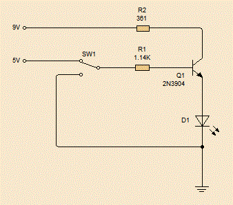
The circuit diagram is this:

Transistor Circuit
The transistor is Q1, the three pins are called the collector, emitter and base.  In our diagram the collector is the top pin (connected to 9V), the base the middle pin (connected to the Netduino pin) and the emitter, which is the bottom pin.

The resistor R2 reduces the power so we don't blow up the LED, SW1 is the Netduino pin, switching between ground and 5V.

The operation is very simple, when SW1 is connected to ground, the resistance of Q1 is high enough for almost no current to flow, so the LED of off.  When SW1 is connected to 5V, the resistance in Q1 plummets and allows enough current to flow to power the LED.

NB: A PNP transistor has a different symbol and doesn't work in this circuit, the resistance doesn't get high enough to turn off the LED.

Also, the resistor R1 is in place for two reasons, firstly, it only takes a small current lower the transistor's resistance as much as it will go.  This is called saturating the resistor.  Secondly, when the transistor changed from low to high or back a pulse of the full voltage and current might be briefly exposed to the Netduino and may damage it, the high resistor stops this pulse from being at a dangerous level.

Tuesday, 7 February 2012

Basic Electronics - Ohm and Kirchoff

It's been a long time since I last looked at electronics equations and whilst I can sort of remember what they are about, I'm finding that it's not nearly as fresh as it used to be, so maybe a small but of revision is needed?  Well it is for me so... back to basics.

Kirchoff's Circuit Laws

These two laws are almost so obvious as that they seem not worth mentioning, that is, when you already know them.

The first is Kitchoff's Current Law, this says that at any node on a circuit the total current leaving the circuit must equal the total current entering it.

KCL
In the diagram above, the sum of all the inputs equals the sum of all the outputs... No matter how many there are!

The second law, is Kirchoff's Voltage Law .  This law states that the potential difference around any loop (closed circuit) must be zero.

KVL
So, in the diagram above, the battery is causing a potential difference of some volts;  Let's say that the battery is supplying 9V, this means that the total of all the voltage drops (or raises, if there was another battery) around either possible loop must be -9V.

Ohms Law

Ohm realised that the current around a circuit was proportional to the potential difference applied to it.  In other words, if you doubled the voltage, then you doubles the current.  He called the coefficient the resistance and gave the equation:

V = I / R

Where V is the voltage, I is the current and R is the resistance.


In the circuit above, the resistors have values of 1,000 ohms and 2,000 ohms.


Circuit with resistors
In order to work out the voltage over each resister we need to work out what the current in this circuit is.

To do that, we need to know how to sum up multiple resistances.  Resisters in series and simple summed by adding their values together, but in parallel equation is:

1/RTotal = Sum(1/Rn)

This means that the total for the circuit is 1666.66 ohms.  Which means that the total current leaving the battery must be I = V/R = 9/1666.66 = 0.0054 Amps.

How is this split when we get to the junction?

I like to work this out by looking at the ration of the resistance.  However, there are two ways and sometimes one is easier than the other.

Firstly, the ratio of the resistors is 1:2 so, 1 third of the current will go through R3 and 2 thirds will go through R2, i.e. 0.0018 Amps through R2 and 0.0036 Amps through R1.  Simple!

Now, the other method.

We need to work out the potential drop across R1 (the voltage drop).  We can use Ohms Law for this, the current  is 0.0054 Amps, and the resistance is 1,000 Ohms so the drop is 5.4 volts.  This means that the drop over R2 & R3 is 9V - 5.4V which is 3.6 volts.

Now, just use Ohms Law again to work out the current through each one.

Current through R2 = 3.6 / 2000 = 0.0018 Amps
Current through R3 = 3.6 / 1000 = 0.0036 Amps

Same result as we got before.

Maybe this isn't allot of help to anyone who's been playing with electronics for a while, but writing it out has helped me refresh this stuff... 

Power

Power, in physics, is a measurement of the speed at which something can do work.  Work, in physics, is the amount of energy something has expended in performing a task and it is measured in Watts.

In an electric circuit, the formular for power is this:

P = IV

Now, look at this basic circuit:


The current in this circuit is I = V / R = 9 / 1000 = 0.009 Amps.  Therefore the power P = 9 * 0.009 = 0.081 Watts


If we substitute Ohm's Law we can see that:

P = IV = I (I * R) = V (V /R)


Next, capacitance!


Monday, 6 February 2012

Shift Register - Hello World


I've just got some shift registers.

NXP 74HC595N


These little chips are very useful for controlling lots of outputs from your 'duino.  Using three pins you can control a massive number outputs.

This chip has 16 pins,  for the sake of this demo, eight of these are the outputs, Vcc & ground, The Master Reset (which we won't use) and then the three pins which are used to control the eight output pins.

OK, this example is very simple indeed.  We'll just get some LEDs to light up to show that we are indeed causing the outputs to change as we expect.


First off, let's look at the datasheet to see what pins do what (look at section 6, "Pinning Information").

  • Q1 (Pin 1) to Q7 (Pin 7) and Q0 (Pin 15), on the other side, are our output pins, we can set these to high or low.  (Q7S is a special output which I'll tackle in another post)
  • Vcc (Pin 16) and GND (Pin 8) 
  • DS (Pin 14), this is the serial input.  This is the pint we use to set the value of each output (Qn).
  • SHCP (Pin 11), this is the clock pin.  This tells the register to accept a new value and shift all the other values over one space.
  • STCP (Pin 12) This is the the 'Storage Register Clock Input', but is commonly refereed to as the latch pin.  This tells the shift register to make the values you've given it live.


OK... First off... acknowledgement!  There's an tutorial here which is for the Arduino.  To be honest, I've done little more than port it to Netduino and re-explain it in my own words.

Speaking of which, let's move on.

Each output pin (Q0 to Q7) has a register which can store a high or low value.   I'm going to call them R0 to R7.  You set these registers one at a time, and each time you set one, all the others shift along one, with whatever was the far end falling off and disappearing.

The clock pin controls this process.  When the clock pin it taken high and then low again it will read whether the data pin is high or low, store this in the first register (Q0's register) and shift all the others along one.  So R1 becomes whatever R0 was previously, until R7's original value is lost completely replaced by whatever R6 was previously.

At the moment, this won't change the value of the output pins; to cause the output pins to reflect what you've loaded into the registers we use the latch pin.  When  this pin is set high, all the values in the output pins are set to reflect the registers.  When it is low, you're free to set registers without changing the outputs.

Wiring

First things first, we'll wire up the LED array which will light up as the output pins go high.

Wiring for the LED array
In this, A through H are the output pins Q0 to Q7 (Don't forget, Q0 is actually on the opposite side of the IC to the other outputs).

Now, Connect the Ground to GND on your 'duin and Vcc to 3.3V.

Now, the tree interesting pins!  Data, clock and latch.  Connect these to your favourite digital IO pins on the 'duino and we're good to move onto the code.

I used the following pins:

  • Latch    D8
  • Data     D12
  • Clock   D11
public static void Main() 
{
        //Pin connected to ST_CP of 74HC595
        OutputPort latchPin = new OutputPort(Pins.GPIO_PIN_D8, false);
        //Pin connected to SH_CP of 74HC595
        OutputPort clockPin = new OutputPort(Pins.GPIO_PIN_D12, false);
        ////Pin connected to DS of 74HC595
        OutputPort dataPin = new OutputPort(Pins.GPIO_PIN_D11, false);

        for (int i = 0; i < 8; i++)
        {
            dataPin.Write(false);
            TickClock(clockPin);
        }

        ReleaseLatch(latchPin);

        for (int j = 0; j < 60; j++)
        {
            Debug.Print(j.ToString());
            dataPin.Write(j % 2 == 0);

            for (int i = 0; i < 8; i++)
            {
                Debug.Print("j = " + j + "\tdataPin = " + dataPin.Read());
                   
                dataPin.Write(!dataPin.Read());
                clockPin.Write(true);
                TickClock(clockPin);
            }
            ReleaseLatch(latchPin);
            Thread.Sleep(499);
        }
    }

    private static void ReleaseLatch(OutputPort latchPin)
    {
        latchPin.Write(true);
        Thread.Sleep(1);
        latchPin.Write(false);
    }

    private static void TickClock(OutputPort clockPin)
    {
        clockPin.Write(true);
        Thread.Sleep(1);
        clockPin.Write(false);
    }
}

The code is quite simple, We load up our registers, alternating high and low.  The TickClock method tells the shift register to accepts the current value of the data pin, save it and shift everything along one.  Once we've written to all 8 registers we call the ReleaseLatch method to activate the state, i.e. make the values in the registers go live.

The end result?


OK, I only had 5 LEDs and as you can see, the rightmost red one is much brighter...  I'll get a better video done at some point.  That is, is the LEDs ever arrive from CHina!

Tuesday, 17 January 2012

555-Timer Hello World

I want to build a device that can measure the capacitance of a bunch of capacitors I have of unknown value.  I realised I had a 555 Timer in my box of random IC's and, looking at how one is fitted together it seems that (in Monostable mode) the output pulse is proportional to the resistor and capacitor (C1 and R1 in the diagram below)

555 Timer (Generated with Livewire)

The length of time of the output pulse is given by the following equation:

R = R1 in Ohms
C = C1 in Farads


Given that in our circuit R1 = 15.4 * 10^3 and C1 = 10 * 10^-6 we can calculate that the timespan of the pulse should be about 0.17 seconds. 

Now that I have a flashing LED, record this pulse width and test the circuit.


NB:  If you're thinking "How does he know the value of R1?", will, resistance is easy to measure, capacitance is not!

I'll update the blog when I've done this!


Sunday, 15 January 2012

Digital IO Using Interupt Events

The previous post showed that we can read the value of D0 by connecting it to D1, setting D1 as an InputPort and using the Read() method.  Whilst this is find for a Hello World demo proving that it works, it's not much good for the real world.  What if we want D1 to report when the value changes?

For this we need to use the InteruptPort, and the OnInterupt event.  Even though the InputPort exposes this event, when you try to wire it up the framework throws one of its ever useful InvalidOperation exceptions.

So, we've got the Netduino wired up just like before, with D0 connected directly to D1, as so:

Pin D0 connected to pin D1

The code for our sample program is then:

namespace DigitalIOHelloWorld
{
    public class Program
    {
        public static void Main()
        {
            OutputPort pinD0 = new OutputPort(Pins.GPIO_PIN_D0, false);
            InterruptPort pinD1 = new InterruptPort(Pins.GPIO_PIN_D1, false, Port.ResistorMode.Disabled, Port.InterruptMode.InterruptEdgeBoth);
            pinD1.OnInterrupt += new NativeEventHandler(pinD1_OnInterrupt);
            while (true)
            {
                Thread.Sleep(1000);
                Debug.Print("D0 = " + pinD0.Read());
                pinD0.Write(true);
                Thread.Sleep(1000);
                Debug.Print("D0 = " + pinD0.Read());
                pinD0.Write(false);
                Debug.Print("Reading D1 = " + pinD1.Read());
            }
        }

        static void pinD1_OnInterrupt(uint data1, uint data2, DateTime time)
        {
            Debug.Print("D1: data1 = " + data1 + "\tdata2 = " + data2 + "\ttime = " + time.ToLocalTime());
        }
    }
}


Now, when the input signal to D1 changes (i.e. when the output from D0 changes) the event is triggered and the Debug statement prints this out.  We can see it's working as every time the we change the D0 output, we see the new state of D1.


The statement gives us three pieces of information.  Look at data2 now though, a value of 1 means that the voltage is high, 0 means it is low.

The Debug information appears in the Output Window, and will look like this:

D0 = False
Turning D0 on
Reading D1 = True
D1: data1 = 28    data2 = 1    time = 01/01/2009 00:13:24
D0 = True
Turning D0 off
Reading D1 = False
D1: data1 = 28    data2 = 0    time = 01/01/2009 00:13:25
D0 = False
Turning D0 on
Reading D1 = True
D1: data1 = 28    data2 = 1    time = 01/01/2009 00:13:26

Digital IO - Hello World

I've just got my Netduino Plus and so some Hello World apps are needed.

There are many examples on how to get your on-board LED to flash, things really get interesting when you can accept input from the pins.  This is a Hello World on reading off the digital pins.

The plan is a simple one.
  1. Connect the D0 to D1.
  2. Have D0 turn off and on.
  3. Read off D1.
  4. See is the value read from D1 matches the value of D0
 I've connected the pins as shown in this picture:

Digital Pins 0 and 1 connected

In order to print out these values, we'll just use the Debug.Print() method, so you'll see it in the Output window of the IDE.  The code used looks like this:

namespace DigitalIOHelloWorld
{
    public class Program
    {
        public static void Main()
        {
            OutputPort pinD0 = new OutputPort(Pins.GPIO_PIN_D0, false);
            InputPort pinD1 = new InputPort(Pins.GPIO_PIN_D1, false, Port.ResistorMode.Disabled);

            while (true)
            {
                Thread.Sleep(1000);
                Debug.Print("D0 = " + pinD0.Read());
                Debug.Print("Turning D0 on");
                pinD0.Write(true);
                Debug.Print("Reading D1 = " + pinD1.Read());
                Thread.Sleep(1000);
                Debug.Print("D0 = " + pinD0.Read());
                Debug.Print("Turning D0 off");
                pinD0.Write(false);
                Debug.Print("Reading D1 = " + pinD1.Read());
            }
        }
    }
}

 Deploying this and running it will produce this output in the IDE:

D0 = False
Turning D0 on
Reading D1 = True
D0 = True
Turning D0 off
Reading D1 = False
D0 = False
Turning D0 on
Reading D1 = True
D0 = True
...


As you can see, the read value on D1 matched the state of D0.

Hope this helps.